Autonomous Camera Assistance for Dexterous Telemanipulation


Project Description
This page outlines the initial research work that I performed at Worcester Polytechnic Institute on the subject of autonomous camera assistance for dexterous telemanipulation task completion. This work aimed to design a viewpoint selection algorithm that would maximize image saliency in the frames shown to the teleoperator. This algorithm was implemented on the Trina2 system developed in the human-inspired robotics (HiRo) laboratory at WPI. This robot features two 7-DOF arms on a mobile robot base. These arms each have a gripper and eye-in-hand camera. The right arm was used as the autonomous camera arm and would seek out a viewpoint that maximized image saliency for the teleoperator. At the same time, the right arm was used as the manually controlled arm for completing the given telemanipulation task. The task designed to demonstrate the effectiveness of saliency maximization was a wall crack repair/inspection. In this task, the user would manually guide the manipulator arm over the cracks within the wall to "repair them", while the autonomous camera arm would seek to maximize saliency within the images selected. The cracks are highly salient as compared to the rest of the wall, so choosing viewpoints that maximize the saliency in a given image should also maximize the cracks seen within a given image. The robot positioned within the tasking environment in the Gazebo simulation environment can be seen in the figure above.
Flask Web-Based Graphical User Interface
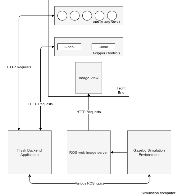
Once the robot was found to be set up correctly within the Gazebo environment, a custom GUI was implemented to allow for direct control of the end-effector's degrees of freedom. This GUI used a web frontend/backend software architecture. In this way, the front end could be easily modified to run on a tablet, mobile phone, or a standard computer, and the back end would work with the front end in each of these cases. The front end was designed using HTML/CSS and JavaScript. The backend was implemented using the Flask micro-service framework, standard ROS packages, and Python bindings. The backend outputs the current state of the front end by publishing standard sensor_msgs/Joy messages over the /virtualJoystick topic. This allows the GUI to be easily extended into other works and applications. The software architecture diagram of the web GUI along with a demonstration video of user input actuating the robot's end-effector Pose can be seen below. The developed software used to run the frontend and backend components of the webGUI can be found in the ROS package here.
Saliency Maximization Viewpoint Selection Algorithm
The saliency maximization viewpoint selection algorithm was designed as a visual servoing algorithm of sorts. This means that the maximum (or local maximums) of image saliency within the environment were found by incrementally moving in the direction of saliency maximization. If no direction would further maximize the saliency in the selected viewpoint, then saliency was said to be maximized. The developed saliency maximization algorithm can be seen in a flowchart form in the image below.

It can be seen that the algorithm can be split into two components, the saliency contour detection portion and the distance minimization portion. The saliency contour detection portion constructs a saliency map of the given frame and finds highly salient regions that fit a set of filtering criteria. From here, the distance between the detected contour center of mass and the center of the image is computed. This process is then repeated with image centers shifted in the four cardinal directions. The original computed distances are then compared to the shifted distances to see what proposed movement would best reduce the overall distance of saliency contours to the center of the image. The direction with the most distances reduced by a given threshold is chosen as the direction to move. The direction to move is used to generate a pose offset in the given direction to the autonomous camera arm's current pose. A demonstration of the saliency maximization algorithm running on a webcam using manual movements from the user in the direction suggested by the algorithm can be seen in the video below. Note that the green blobs are filtered saliency contours, the black lines represent the distance between the contours COM, and the red arrow is the suggested direction to move.
This same algorithm was run using images taken from the autonomous camera arm of the TRINA2 robot arm. Unfortunately, the time required to generate and execute trajectories by the MoveIt! motion planners resulted in the image topics needing to be throttled down to sub-hertz frequencies. Due to this system limitation, the responsiveness of the robot to saliency information is jerky and infrequent. This algorithm can be seen running on the Trina2 system in the video below. The generated saliency maximization algorithm can be found in the ROS package here.