6-DOF Wireless Pose Capture System


Project Description
In some of my graduate research efforts, I was able to create a wireless 6-DOF pose capture system to serve as a human-robot interface. This system makes use of a hand-held vision target tracked by an Intel RealSense depth camera to capture target position in 3D space, and a BNO055 absolute orientation sensor to capture the vision target orientation. In this sense, the vision target orientation and position are captured as independent data streams that can be fused into one 6-DOF pose data structure. All developed hardware, firmware, and software can be found in the GitHub repository here. Please see the overall system high-level block diagram below.

Position Capture Subsystem
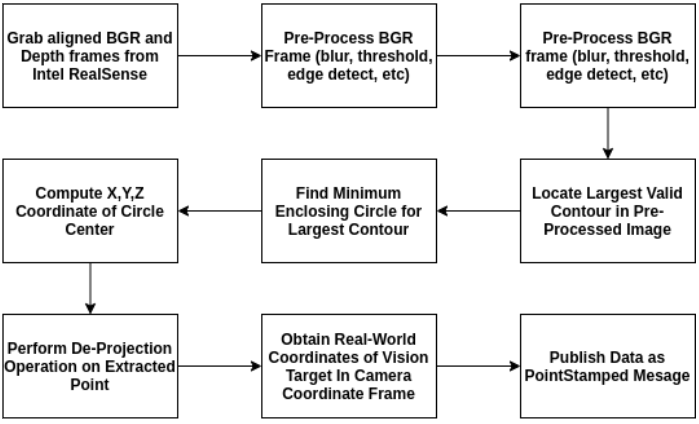
We will now look at some more in-depth details on the position capture portion of the system. As previously mentioned, a hand-held vision target is tracked as a means of allowing user input from the motion of said vision target. An Intel RealSense depth camera is used to track the real-world X, Y, and Z position of the vision target within the camera reference frame. Once the real-world position of the vision target is extracted, it is smoothed using a windowed average to help remove sudden jumps in detected position due to noise. The overall image processing pipeline can be seen in the figure below.
Orientation Capture Subsystem
The orientation capture sub-system obtains the orientation of the vision target through the use of the BNO055 absolute orientation sensor. Data obtained from the orientation sensor is wirelessly streamed to a base station through a pair of NRF24L01 transceivers. Once the data reaches the base station MCU, it is streamed into the base station computer through a serial interface. A custom PCB was designed to manage power delivery and communication with the BNO055 sensor on the vision target, as well as facilitate wireless communication with the base station. This PCB will be examined in more detail in a later section. Both the orientation capture component level architecture and orientation data transmission flowchart can be seen below.


System Hardware and Firmware
The orientation capture sub-system obtains the orientation of the vision target through the use of the BNO055 absolute orientation sensor. Data obtained from the orientation sensor is wirelessly streamed to a base station through a pair of NRF24L01 transceivers. Once the data reaches the base station MCU, it is streamed into the base station computer through a serial interface. A custom PCB was designed to manage power delivery and communication with the BNO055 sensor on the vision target, as well as facilitate wireless communication with the base station. This PCB will be examined in more detail in a later section. Both the orientation capture component level architecture and orientation data transmission flowchart can be seen below.


The aforementioned base station was composed of an Arduino Uno and NRF24L01 module. These components were housed within a 3D-printed base station case. This system, along with its rough schematic representation can be seen in the figure below. The firmware, electrical, and mechanical hardware designed for use in this project can be found in this GitHub repository.


Overall System Demo
Once both the orientation and position data streams have been fused on the base station, the generated Pose is published throughout the system. I have created a demo in which the Pose of a box within a gazebo simulation environment is set dynamically using live data from the pose capture interface. Please have a look at this video below.